Send DX Hints or Kinks to any of the Blog Authors shown below.

Sunday, March 19, 2017

Using HFTA for Site Evaluation - Part 2


We continue with Charlie, N8RR's, article about the use of the HFTA software.  We will publish this in three parts here on the WVDXA Blog.  
This is Part 2.

==========

How Accurate is HFTA?
In 2007, the answer to this question was unknown to me.  Having operated from hilly terrain for much of my radio career, I had some preconceived notions about some of the terrain effects and the results of the initial HFTA runs looked reasonable to me.  For example, the general positive effect of sloping hillside under an antenna was known to me; I had successfully placed antennas on hillsides for years to favor a desired direction.   The concept of a hilltop antenna being too high was also known; W8NR’s (SK) hilltop 20M monoband yagi was simply not competitive in a DX contest we once operated from his QTH.   Contrast that with observations from W8AH (SK) who had a dominant signal on all bands using antennas that were at modest heights compared to many other big gun stations.  Al Hix figured out long ago how to use the terrain to his advantage. 
The software author made no extravagant claims regarding the absolute accuracy of HTFA predictions.  The software performance in rugged complex terrain was also unknown.   In 2007, I thought HFTA would be useful for comparing antenna locations and heights in terms of gross results but that it could not be used to fine tune choices.  The author did not claim accuracy better than 3 dB.  HFTA was used to judge the gross performance differences between options.   If the software said one option was 2 or 3 dB better than another, I paid attention.   If results were within a dB or so, the result was treated as equal.  
It is now 2017 and many HFTA studies have been done for myself and others.  To verify software predictions, a considerable amount of on-site testing was performed. The software limitations are now better understood.  Overall, HFTA is a useful tool if one has options for placing antennas.   It can also be used to evaluate the gross effect of stacking antennas on existing towers.  Depending on the terrain, stacking antennas does not always do what you would expect. 
Limitations

All computer models are simulations.  The modeling results are only as good as the underlying assumptions and the accuracy of the data input. 
The earth and terrain, especially in front of the antenna, are an integral part of the antenna system.  The main elevation lobe is formed by a combination of the direct ray with the earth reflections from below and in front of the antenna.   The earth reflections reinforce or cancel the main ray depending on the phase relationship.  Standard models show the development of the main lobe over level ground.   If the earth around and in front of the antenna is not flat, the elevation angle and amplitude of the main lobe can be drastically different from the flat earth case. 
The terrain data used by HFTA to calculate the main lobe amplitude and elevation is an approximation.   The software looks straight ahead to points on a given azimuth line, out to about 14,000 feet from the tower base.  The data file for each radial fan consists of a series of 147 spots, each representing distance from the tower and elevation at the spot.  It is these point elevations where the real variability can occur, because they are derived from USGS data which is based on fairly wide intervals.   For example, most elevation contours are on 10 meter intervals and some still use 30 meter intervals.  
The electronic USGS elevation for my tower base was off by 20’ on the low side in the initial runs. The problem was discovered and a new USGS file was obtained with correct data.    Comparing the HFTA results between the two runs, the numbers are significantly different but the general conclusions reached about options were unchanged. 
HFTA can never predict an exact gain or an exact elevation angle, if all else is perfect with the software.   Given the terrain accuracy limitations, HFTA does a good job of predicting performance differences between antenna options in gross terms.   Don’t expect to use it for fine tuning antennas that are within a dB or so of each other. 
The software uses elevation angle statistics calculated by VOACAP for an entire solar cycle on a given band from your general geographic area to a specific target area.  HFTA uses these elevation statistics, which indicate what percent of the time a signal arrives at a given elevation angle, and compares this info to your elevation plot, generating a relative performance rating called Figure of Merit, expressed in dB.   The software will tell you which antenna option will work the best, on average, to a target area (such as EU).  These are approximate because of the terrain limitation AND the elevation statistics are an estimation. The FOM rating is interesting and useful for gross comparison, but I prefer to look at the actual elevation plot.  
What I like to see is a high gain elevation lobe, at as low of an angle as possible.   What one sees in a positive terrain enhancement situation is a substantial portion of the main lobe that falls in elevation below the main lobe of a flatland antenna.  My point of view is that of a DXer, not a contester, who may have other preferences for elevation angle.
There are other limitations which may introduce variability in the results.  The software is looking straight ahead on a line of points.  The antenna is illuminating the ground in a broad swatch.   Terrain behind and to the side of the antenna is not considered.  The software would become overly complex if these other terrain factors were considered. 
When evaluating stacked antennas, the software author N6BV cautions the antenna spacing must be at least ½ wavelength. If closer spacing is used, HFTA will give an inaccurate (inflated) result. 
The most complex part of HFTA was obtaining the electronic terrain file needed to draw the radial fans.  An electronic Digital Elevation Model (DEM) was downloaded for the quadrangle in which the QTH was located.   Microdem, a mapping program that came with HFTA, was used with the USGS DEM to plot an approximate 14,000’ long radial (also called fan) every 5 degrees around the compass rose. 
Using HFTA in 2017 is easier because the process of generating the radial fans has been automated by K6TU.  All that is needed is to enter a set of coordinates on K6TU’s site and within minutes the resulting radial fans will be emailed as a Zip file.  Microdem is no longer needed by the end user and it is not necessary to know the name of your USGS quadrangle.  The K6TU files generate radials in 1 degree increments.  What once was complex is now simple.  This service is free but one needs to register.   http://k6tu.net/
Sample Charts
There was good news and bad news at N8RR.  The good news was that some of the prime directions were predicted to have significant terrain enhancement.  Additional good news was that optimum height for the good directions was fairly low.  I would not need to deploy the stacks as planned.   The bad news was that some directions have negative terrain consequences, worse than a flat land antenna.  In the bad directions, there was nothing practical that could be done to overcome the terrain, including going higher or stacking.   
Based on the initial review, the site would be an excellent location for DXing in some prime directions.  In other directions, it would be average, and in a few it would be at a competitive disadvantage to a flat land station.  
===== Note: Click on any image to see it larger. =====
20 Meters - 45 Degree Azimuth - Stacked C31XR Antennas
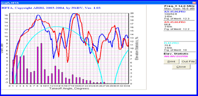
There is NO significant improvement to EU predicted on 20M for the stack over a single lower antenna.  It turns out 56’ is about the optimum height on this tower site for 20M.   The single 56’ high antenna was expected to be a great performer to EU on 20M, outperforming the same antenna at 75’ on flat ground by 2.2 dB Figure of Merit (FOM).  The feature I like to see is the shift of the elevation curve favoring lower angles compared to the flat land antenna. 
The next graph shows what the predicted 10M performance of the original stack concept would have been at 100’ and 50’, the performance at 56’ for a single antenna, and the performance of the 10M antenna at 25’:

For purposes of this comparison, a 3 element antenna was used, although the C31XR has 7 elements on 10M.  Note the stack was only 1 dB better FOM than the single antenna at 56’ although the low angle performance was significantly better for the stack. The FOM for both of these options was significantly worse than for a 10M antenna at 25’ on this tower.  The low angle performance of the low antenna was roughly comparable to the 100’/50’ stack.   HFTA was indicating the 10M antenna needed to be lower on this hilltop tower.    The 15M comparison was similar to 10M.  

TERRAIN FACTORS AT N8RR CAUSING ENHANCEMENT OR DEGRADATION
Here is a terrain profile which results in enhancement compared to a flatland antenna, 45 degrees toward EU from the 56’ Rohn 45G tower: 

Note the vertical scale is drastically compressed compared to the horizontal scale, which exaggerates the terrain features.  It is not as bad as it looks!   The dominant feature which creates positive enhancement to low angle radiation is the steep drop in elevation immediately under the antenna.  The situation is not as good as it could be because of the approximate 825’ ASL parallel hill at about 1500’ in front of the antenna and in particular the higher 1,020’ hill about 4,000’ out.  The later terrain feature impinges on the lowest angles and is close enough to detract somewhat from the performance.   As the antenna turns clockwise from 45 degrees toward the east, this particular ridge feature moves closer to the antenna and progressively blocks the lower angles, until at about 90 degrees azimuth the performance is seriously degraded.  On the other hand, as the antenna turns north from 45 degrees, the major blocking ridge moves out of the field and the low angle performance recovers.   Here is the 90 degree terrain profile:
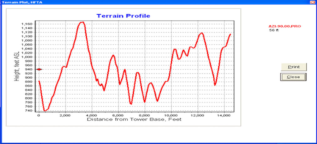
Again, this looks worse than it is because of the compressed vertical scale. However, it is bad enough, and all HFTA predictions looking east show significant degradation compared to a flatland antenna. 

The above chart shows the blockage of low angle signals to Africa at 90’ with the 56’ high antenna (blue line).  The red line shows a 100’ high antenna would be significantly worse than the lower antenna.  The light blue line shows a 100’ antenna on flat ground.  This chart illustrates what terrain degradation looks like.
If we turn toward the north from 45 degrees, the story changes.  Here is a look at 10 degrees:

Higher terrain features are out over a mile from the antenna.  This is far enough to avoid degradation compared to a flatlander and preserve the enhancement from the steep ground slope under the antenna. 
Here is the chart for the C31XR at 56’ looking toward Asia at 10 degrees azimuth, compared to a flatlander at 100’:

Note the big elevation lobe peaking to the left of the flatland elevation lobe.  The low antenna on the hilltop should dominate the 100’ antenna on flat ground.   The FOM, for what it is worth, is 4.5 dB higher for the hilltop antenna.  This is what a favorable terrain situation looks like.

***** This description of HFTA will be finalized in Part 3 *****

Post written by: Charlie, N8RR

Tuesday, March 14, 2017

Using HFTA for Site Evaluation - Part 1

Charlie, N8RR, has written a very detailed article about the use of the HFTA software.  We will publish this in three parts here on the WVDXA Blog.  This is Part 1.

==========

Summary

HFTA is available bundled with the ARRL Antenna Book. 
What is HFTA?  HFTA or HF Terrain Analysis is a software program developed by Dean Straw, N6BV when he was the handbook Editor at ARRL is available bundled with the ARRL Antenna Book. 
HFTA models horizontal antennas (dipoles, simple yagis, stacked yagis) at specified heights over terrain and plots the modeled antenna gain at different elevation angles.
A description is provided here of how HFTA by N6BV was used to evaluate and implement antenna options at the N8RR site in West Virginia.  Links are provided for other sources describing the features of HFTA, how to acquire it, and how to interpret the graphs so this information is not repeated.  Site evaluations for friends were performed using HFTA and some of the results are described.  The photo at the right shows a Google Earth image of N8RR's QTH.  You can plainly see his three towers.  To get a feel for his terrain, the red roofed house in the upper right is 152-feet below the base of his Rohn 45G tower and is just 447-feet away (at a heading of 43.4°).  Click on any photo to see a larger image.
N8RR QTH - Red Roof House is 152' below N8RR's Tower
Based on the experience gained using HFTA, the general usefulness of the software is evaluated and the limitations are presented.  General conclusions about antenna placement on complex terrain are provided; these are the author’s conclusions only.
This work was not an attempt to scientifically validate HFTA or the absolute accuracy of the software conclusions.  Please see the later section on Limitations. 
A considerable amount of on-site A versus B testing was done at the N8RR QTH over several years.   The testing was not conducted in a scientifically rigorous manner.  The goal of the testing was to satisfy the author that HFTA predictions of relative performance differences between local antennas were valid. In nearly all cases, the A versus B tests were conducted in receive mode. Thousands of tests were done.
HFTA predicts the takeoff angle and amplitude of the transmitted lobe.  Using received signals may not always provide a true reciprocal comparison. When HFTA predicted an antenna option would be best in terms of main lobe amplitude at useful angles, the prediction was considered to be confirmed if the received DX signal was consistently stronger on the receiver S meter.  Signal to noise ratio improvement was not considered as proof although there were many times when the local noise pickup profiles of the antennas were drastically different.

Who Should Use HFTA?
Here is a beginner’s guide to using HFTA:  
HFTA is useful for those who have irregular terrain features, such as sloping ground, surrounding hills, etc., and who have options for placing towers/antennas.  If you don’t have options for changing tower locations, changing antenna height on existing towers, or stacking antennas on an existing tower, HFTA will provide no actionable data. 
HFTA does provide interesting results.  After looking at dozens of sites, and recognizing DX success is partially psychological, I no longer volunteer to use HFTA if I think a site might have some issues. What is the point of telling a friend his existing antenna is performing significantly below par because of a terrain feature that he can do nothing about?   DX can be worked from just about any location.  Operators should focus on that and not conclude, based on a software prediction, their antenna is bad and thus it is not worth trying to work DX.  
The opposite is true if I think a location has terrain enhancement.  Sometimes I can convince a friend his location is better than average based on HFTA results.  He might become more motivated to chase DX as a result.  
For antennas situated on flat ground, with no terrain features within 14,000’ of the tower, there is not much to be gained from HFTA except for evaluating stacks.  EZNEC might be more accurate for modeling stacks over flat ground but HFTA will calculate, using propagation statistics, a Figure of Merit (FOM) to a given target area from each antenna; this rating might be interesting.  For example, the FOM might predict your 150’ high yagi is too high for EU on average.  You likely already know that.  You can evaluate adding stacked antennas with HFTA to see the effect on the FOM or on the main lobe amplitude and elevation angle.  You can also evaluate the individual antennas in a stack.  
   
BACKGROUND    
I retired from paid work at the end of July 2008.  Two years before retiring, we moved to a WV hilltop.  These last two working years required 100% travel except for weekends and holidays.  Evening downtime on the road was used to work DX from the mobile and plan the future antenna installation in WV.  Before discovering HFTA a plan was devised to install a 100' Rohn 45G tower and stack two C31XR's at 100' and 50' along with a Force 12 Delta 40/30 on top of the mast.  The antennas were purchased in 2007.
My terrain fits the definition of complex.  The elevated site looked like a good radio location.  This was confirmed with a 100W mobile rig and screwdriver antenna in September 2006, my first experience with HF mobile.  Having always heard there were HF hot spots, the new QTH seemed to be one.  When traveling up the main driveway from the valley highway below, the signals could be heard building in my receiver.  The effect was dramatic.  I couldn’t wait to try a real antenna.
HFTA was discovered in 2007 before any antenna work was done and it provided a detailed understanding of the general opportunities and problems with the site.  Many dozens if not hundreds of hours were put into planning with HFTA before the first tower was erected. 
Having lost interest in contesting I decided to focus on serious DXing.   After spending the time with HFTA, my plan was modified after the software said a 100' tower was too high for my terrain on any band 40 through 10 meters and  56' and 62' were optimum heights for 20 and 40 respectively, looking in my most favorable directions.   HFTA also predicted 56’ was too high for 15 and 10 meters on my hill.  I chose to install a C31XR at this height anyway for the first tower install, just to get on the bands.
The Rohn 45G was installed in June 2009, with a C31XR at 56',  a Force 12 Delta 40/30 at 62' and a 7 element M2 6M7JHV for 6 meters at 68'.  The results from this system were great on 40/30/20.   My antennas look down on STEEPLY sloping terrain in all directions, and from about 300 degrees clockwise to about 50 degrees, there are no higher terrain features out a few thousand feet. 
After about 50 degrees going clockwise around through west, even though we have steep terrain drop under the antennas, there are very close in hills which rise up steeply from the valley floor below; in some cases these ridges  go to an elevation 100' or more higher than my hilltop.  These are my problem directions as predicted by HFTA.  The low angles tend to be cut off below 4 degrees or so, and the first lobe is pushed up to a higher elevation angle.  The effect seems worse on the higher frequencies. On several azimuth headings affected by the nearby higher hills, HFTA predicts my antenna performance is significantly below that of an equivalent flat land installation. 
In complex terrain like WV, there are three possible outcomes. One can be the beneficiary of terrain enhancement, where the antenna clearly outperforms.  One can be a situation where the rugged terrain is not a huge positive or negative factor, and performance on a par with level ground can be achieved.  Last, the terrain can be a huge negative, and nothing short of a costly and heroic effort can achieve good DX performance.  See the K8KT example discussed later. 
Having no antennas with which to do side by side comparisons, I judged the 40/30/20 meter performance of the initial setup to be excellent.  The signal felt loud in my favorable directions as predicted by HFTA.  I could easily run EU/AS stations and break pileups with ease.  The propagation was down on 15 and 10M the first year, but I could work DX stations.  Perhaps it was psychological but the high band results did not seem competitive with others in my area. Likewise, the results in my terrain challenged directions were much inferior to my good directions, especially on the high bands.  I had to work HARD to break pileups, especially on 10M.  DX could be worked, but not in the easy manner like in the favorable directions.
After using my first system for several months, I had to test the HFTA prediction that a lower antenna would be better on the higher bands in my favorable directions.  A reference 2 element quad was built on a 29' tower, which was placed in a location 80’ from the first tower, in a position closer to the cusp of the hill looking N/NE.  The quad, which was optimized for gain on EZNEC, used an 8' boom and covered 17/15/12 and 10 meters. 
Many hours were spent doing A versus B comparisons on 15 and 10 meters between this quad and the higher C31XR.  The small quad was consistently better to EU and AF on 10 and 15 meters than the C31XR, which has 4 elements on 15 and 7 on 10, each band using 25' of the boom length.  This result was despite the quad having lower isotropic gain on each band.  There was never a time to EU or AF where the higher C31XR beat the quad, and not many times when the result was equal.  HFTA successfully predicted this performance favorability for the low antenna at this height and in these directions. 
HFTA also said the higher yagi would be better than the lower quad looking straight north to Asia and also to the Pacific. This prediction also proved to be consistently accurate.   As far as I was concerned, the comparisons on 15 and 10 meter with the reference quad and C31XR completely verified the HFTA prediction.
For one practical example, ZD7XF was on CW and the Challenge point was needed on 10 and 15M.  HFTA predicted the lower quad would be best, an unambiguous call.   Sure enough, and without any doubt, the quad beat the yagi.  In fact, my Q's on 15 and 10 with ZD7XF had to be made on the quad, because the conditions were too marginal for the higher antenna to hear ZD7XF very well.  
Another practical example was particularly convincing.  My C31XR at 56' worked well on 17M using a tuner, and we made DXCC with it easily in a few months. The yagi models in EZNEC to have about the same gain as a dipole on 17M, favoring the normal reflector end of the antenna.   However, the 2 element quad on 17 walked all over the C31XR, in real life and the HFTA model, in every direction except one.  HFTA predicted the C31XR, modeled as a 17M dipole, would consistently beat the 2 element quad to the Pacific and VK/ZL.  There was never a test where the quad beat the yagi (dipole) on 17M to these directions.  
Some testing was done on 6M. The M2 6M7JHV was (still is) at 68' on the Rohn 45G tower. A 6 element Hy-Gain yagi was temporarily installed at 17' fixed NE on the same tower.  HFTA predicted the low antenna had much superior gain in the first lobe and a lower elevation angle compared to the high antenna, looking NE.  The install occurred after the EU Es season.  All of the North America AU and Es signals from the NE that year were louder on the lower antenna.  The second year, the first Es EU QSO's were made on the low antenna, which was much better than the high one.  After that, the low antenna developed a problem and was removed from service.  The limited testing seemed to confirm the HFTA prediction that lower is better on 6M on my hill.  More future testing is planned.  In the meantime, the 6M7JHV produced a 6MDXCC on E skip from scratch in 6 years.    
Although I was satisfied with the HFTA predictions, at least for my hilltop, more optimization of the antennas was needed and this created the opportunity for more HFTA validation.  A location was picked, using HFTA, for a TX-455 crankup tower.  This spot seemed to have the best modeled performance on the higher bands because the antenna could see the down sloping terrain in all directions.  The short quad tower was situated on the NE lip of the hill, and it was looking across the level yard to the west; the quad could not see the down slope on the west side of the hill.  The first antennas on this crankup tower were a 5 element M2 17M5 yagi for 17M and a Hy-Gain 125CA 5 element 12M yagi.  Now we could compare predictions for the 2 element quad on 17M and 12M with the monoband yagis in A versus B tests.
Generally, the HFTA predictions were confirmed as valid.   There were directions (NE) where the quad was predicted to equal or be even slightly better than the big yagi on 17M, which has a 36' boom. However, the performance comparison between these antennas did not justify keeping 17 and 12 meter elements on the quad.  With a desire to increase gain on 15 and 10M, the two element quad was rebuilt with a longer (18') boom and with three elements covering only 15 and 10 meters.   EZNEC was used to manually optimize the gain at the expense of front to back ratio.  After the revised quad was installed, comparisons with the C31XR in A versus B tests continued to confirm the HFTA predictions; the lower antenna was better on 15 and 10 meters.   
Before taking down the 2 element version of the quad, I decided to rotate the boom 90 degrees to test the antenna with vertical polarization compared to the big yagis.   With the feedlines attached to the spreaders, the quad was in significant mechanical stress.  However, some signal comparisons were made.  I wanted to see if vertical polarization made any improvement in the terrain challenged directions.  No improvement was noted and, in fact, during the limited testing the vertical polarization on the quad was never as good as any of the horizontal yagis on any band. 
With the completion of the 3 element quad on 15 and 10, we were in good shape antenna-wise, except the quad on the low tower could not see the west hill slope.  This negatively affected the performance to the Pacific and VK/ZL.  The C31XR on the higher tower was best looking west on the high bands.  Raising the low tower so the antenna could see the west slope eliminated the advantage the quad had for the E/NE.  Another round of antenna changes was planned.
A decision was taken to improve 15/10 meters overall, while also improving 20M.   HFTA said the optimum tower for 17/15/12/10 in all directions was the TX-455 crankup, because it could see the hill slope in all directions.  The following changes were made:
1.  The 17M yagi was removed from the crankup tower.
2.   The C31XR was moved from the Rohn 45G tower to the crankup tower on the bottom mast position.  The 12M yagi remained in place at the top of the mast.
3.   A M2 20M5 5 element monobander for 20 meters was installed at 56' on the Rohn 45G, replacing the C31XR.
4.   The big 17M M2 antenna was moved over to the short tower on the east side of the hill, replacing the 3 element quad. 
The result of the changes was positive on all bands except 17M.   The antenna was a world beater to the N/NE on the low tower, but the performance was compromised to the west due to not seeing the western hill slope. Raising the antenna would have fixed this problem, but it would have negatively impacted performance to the N/NE.   Occasionally the C31XR, as a 17M dipole, will beat the big yagi looking west. 
After the above changes, I could no longer do A versus B comparisons on 15 or 12 meters. However, for the first time, tests with two 20M antennas could be done.
The crankup tower was operated at a height of 30’ to 35’ to maximize performance on 15/12/10 meters.   I thought this would detract from 20M performance, but HFTA said the 3 elements on the C31XR would work great on 20M.  There is 2.1 dB more isotropic gain on the big 5 element antenna.  Depending on the direction, there is sometimes no detectable difference by ear between these antennas.  In other directions, the bigger, higher antenna is best. The QSB cycle on a signal will sometimes favor one antenna over the other momentarily, and then at the next moment switch over to favor the other antenna.  HFTA is able to consistently predict which antenna will be best on average if there is a best antenna on the path.   
After a couple of years operating in this last mode, one other change was made.  I decided to modify the small tower and placed a 105CA Hy-Gain 10M monobander at 25' and raised the 17M yagi to the top of the mast at 35'.  This later change negatively impacted the NE performance on 17M slightly, but helped the performance to the west.  It was a good compromise.  On 10M, the low yagi on the east tower is consistently better to the NE/E/SE than the C31XR over on the crankup tower.  The performance differences on 10M continue to be accurately predicted by HFTA between these two antennas, with one exception.  The C31XR cannot see local earth SE of the tower due to the placement of my house.  In all cases, signals from the SE/S looking over my house from the C31XR are attenuated by 20 dB compared to the 10M antenna on the east tower.  HFTA does not account for man-made obstacles!  This S/SE degradation from the C31XR only occurs on 10 meters; it does not seem to be present on 15M or 12M.    
Other potential improvements have been contemplated, such as replacing the F12 Delta 40/30 with large monobanders.  I run hot and cold on this.  So far, I have not been able to justify the work and cost considering how well the existing antennas perform.  The terrain enhancement predicted by HFTA to the N/NE seems to exist on 20/30/40 meters. N8RR was the first NA QSO with T6MO (K9GY) when he first became active and finished leading the NA Clublog leaderboard to Eric.   When T6LC came on the bands, he offered one of his combat medals to the first 5 NA QSO's.  This terrain resulted in 2 of the first 5 NA QSO’s (on 40 and 20M) with T6LC. 

***** This description of HFTA will be continued in Part 2 *****

Post written by: Charlie, N8RR